STP (Spanning Tree Protocol)
Introduction
In this guide, we will quickly explain what the Spanning Tree Protocol is and give an example implementing it.
The Spanning Tree Protocol or STP is a network protocol that operates on the Layer 2 level of devices.
The ports on a switch with STP enabled will always be in one of the following five port states.
-
Blocking
-
Listening
-
Learning
-
Forwarding
-
Disabled
The ports in a switch with STP will often begin in the blocking state and later change to the listening, learning, and eventually forwarding state when appropriate.
This conversion may take time as devices “learn” where other devices are.
STP is simple to implement using bridges and is important to address looping and wasting bandwidth. STP works by blocking redundant links from forwarding packets.
To learn the basics of bridges, visit the following: Bridging Layer 2
Enabling Spanning Tree Protocol
By default, STP is disabled on all bridges.
To enable STP on an existing bridge, run the following command:
$ ip link set dev ${Bridge Name} type bridge stp_state 1
To enable STP on bridge creation, use:
$ ip link set dev ${Bridge Name} type bridge stp_state 1
To disable STP on a bridge, set stp_state to “0”.
To show the current information about the state of the bridge use the following:
$ ip -d link show dev ${Bridge Name}
The brctl utility can also be used to view information about the current configuration.
If the brctl utility is not already installed:
Do not forget to use $ apt-get update to fetch the latest version of your package lists. Follow this with the command $ apt-get upgrade to first review the changes in the latest versions and then replace the old packages by installing the new ones.
Install the brctl utility with: $ apt-get install bridge-utils
Use the following to confirm STP is enabled:
$ brctl show ${Bridge Name}
In addition to this, view other relevant information regarding the STP configuration of the current bridge with:
$ brctl showstp ${Bridge Name}
Configurables
The following are some of the controllable parameters regarding STP configurations
- Bridge Priority
- Path Priority and Cost
- Forwarding Delay
- Hello Time
- Max Age
Bridge Priority
The Bridge Priority is used to determine the probability that the bridge will be elected as the root device. A lower bridge priority indicates that a switch has a higher likelihood of becoming the root device
Ex.
$ ip link set ${Birdge Name} type bridge priority ${Priority Number}
Path Priority and Cost
The Path Priority and Cost will influence the route packets take. A lower cost is preferred.
Ex.
$ ip link set ${Interface Name} type bridge_slave cost ${Cost Number}
Forwarding Delay
The Forwarding Delay is the time spent in hundredths of a second in the LISTENING state and the LEARNING state before changing states.
Ex.
$ ip link set ${Bridge Name} type bridge forward_delay ${Delay Time}
Hello Time
The Hello time is the set of time in hundredths of a second between each hello packet sent by the bridge.
Ex.
$ ip link set ${Bridge Name} type bridge hello_time ${Hello Time}
Max Age
The Max Age is the timeout requirement for the hello packet. It reflects the time in hundredths of a second until another bridge in the spanning tree is assumed to be dead. It is based on the time of reception since the last received hello message.
Ex.
$ ip link set ${Bridge Name} type bridge max_age ${Age Time}
Example Configuration
Consider the following topology:
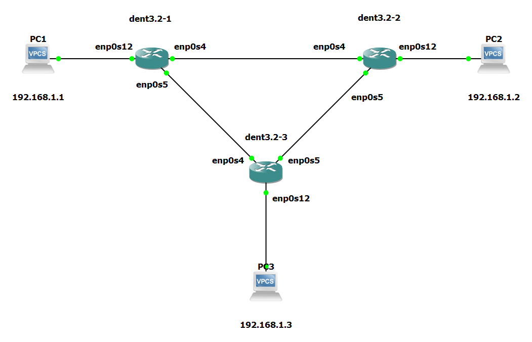
Let’s say we wanted to configure PC1, PC2, and PC3 to be able to communicate over these links and maintain the same LAN. One way we could do this is to create bridges on every switch and enslave all the connected interfaces.
However, creating a bridge on every device without STP enabled would begin to flood the system, as shown below.
Flawed Example:
The following was run on every switch in the given topology:
$ ip link add name br0 type bridge

$ ip link set enp0s4 master br0

$ ip link set enp0s5 master br0

$ ip link set enp0s12 master br0
The interfaces were also brought up with:
$ ip link set enp0s4 up

$ ip link set enp0s5 up

$ ip link set enp0s12 up

$ ip link set br0 up
The result of this configuration was a flood of requests in the system. The following is a log from one of the switch devices:
root@localhost:~# [  291.521985] br0: received packet on enp0s4 with own address as source address (addr:0c:6e:09:a1:00:01, vlan:0)
[  291.530112] br0: received packet on enp0s4 with own address as source address (addr:0c:6e:09:a1:00:01, vlan:0)
[  291.537694] br0: received packet on enp0s5 with own address as source address (addr:0c:6e:09:a1:00:01, vlan:0)
[  291.554573] br0: received packet on enp0s4 with own address as source address (addr:0c:6e:09:a1:00:01, vlan:0)
[  296.510152] net_ratelimit: 6194 callbacks suppressed
In this configuration, attempting to add a bridge to every device without STP enabled resulted in a loop where devices where receiving their own source MAC addresses.
To avoid this, enable STP by including stp_state 1 upon bridge creation.
Corrected Example:
The following was run on every switch in the given topology:
$ ip link add name br0 type bridge stp_state 1

$ ip link set enp0s4 master br0

$ ip link set enp0s5 master br0

$ ip link set enp0s12 master br0
The interfaces were also brought up with:
$ ip link set enp0s4 up

$ ip link set enp0s5 up

$ ip link set enp0s12 up

$ ip link set br0 up
By enabling the bridges to include STP, the system flooding was prevented. PC1 PC2 and PC3 can now successfully ping one another without the switches receiving continued feedback regarding their own source MAC addresses.
PC1 : 192.168.1.1 255.255.255.0

PC1> ping 192.168.1.2

84 bytes from 192.168.1.2 icmp_seq=1 ttl=64 time=2.345 ms
84 bytes from 192.168.1.2 icmp_seq=2 ttl=64 time=1.093 ms
84 bytes from 192.168.1.2 icmp_seq=3 ttl=64 time=1.442 ms
^C

PC1> ping 192.168.1.3

84 bytes from 192.168.1.3 icmp_seq=1 ttl=64 time=0.506 ms
84 bytes from 192.168.1.3 icmp_seq=2 ttl=64 time=0.713 ms
84 bytes from 192.168.1.3 icmp_seq=3 ttl=64 time=0.728 ms
84 bytes from 192.168.1.3 icmp_seq=4 ttl=64 time=0.878 ms
^C
PC3>
NOTE: The outputs above were tested on a Virtual Machine